
Monday, February 27, 2023
Piping Work
Cerafiltec


Pneumatic Actuator

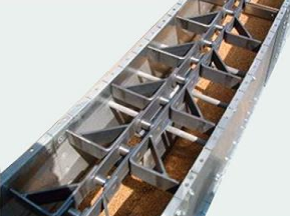
Conveyor Belt


Wednesday, February 22, 2023
Belt Filter Press


PRINCIPLES OF DIMENSIONING
Dimensioning is an essential part of technical drawings and engineering design. It involves the process of adding measurements and annotations to drawings to communicate the size, location, and tolerances of objects, features, and components. Here are the principles of dimensioning:
Clarity: The dimensions should be clear, precise, and unambiguous. The units of measurement should be specified, and the placement of the dimensions should be logical and easy to read.
Consistency: The dimensions should be consistent throughout the drawing, using the same style, font, and placement. This makes it easier to read and understand the drawing.
Accuracy: The dimensions should be accurate and match the actual dimensions of the object being depicted. This is critical to ensuring that the final product or component will function correctly.
Completeness: All necessary dimensions should be included on the drawing, including the size, shape, location, and orientation of features, as well as tolerances and other specifications.
Appropriate dimensioning: Dimensioning should be appropriate to the type of object being depicted. For example, circles should be dimensioned with diameter, while rectangular objects should be dimensioned with length, width, and height.
Simplicity: The dimensions should be as simple and clear as possible, using as few dimensions as necessary to convey the required information. This helps to reduce the likelihood of errors and confusion.
Tolerance: Tolerance is the acceptable deviation from the specified dimension. Tolerances should be specified to ensure that the final product or component will function correctly and fit together with other components.
By following these principles of dimensioning, engineers and designers can create clear and accurate technical drawings that can be easily understood and used to manufacture products and components.
TITLE BLOCK
A drawing title block is a section of a technical drawing that contains important information about the drawing, such as the title, author, date, scale, and revision history. Here are the common elements found in a drawing title block:
Drawing title: The title of the drawing provides a brief description of the subject matter and purpose of the drawing.
Author: The name or initials of the person who created the drawing.
Date: The date the drawing was created or last modified.
Scale: The scale of the drawing indicates the ratio between the size of the drawing and the actual size of the object being depicted.
Drawing number: A unique identifier assigned to the drawing for tracking and referencing purposes.
Company logo: The logo of the company or organization responsible for the drawing.
Sheet size: The size of the drawing sheet, typically specified in standard sizes such as A0, A1, A2, etc.
Revision history: A table that records the history of revisions made to the drawing, including the date of each revision, the reason for the revision, and the initials of the person who made the revision.
Notes: Additional information or instructions related to the drawing, such as specifications or standards that must be followed.
The title block is typically located in the lower right-hand corner of the drawing sheet, although its exact location and size may vary depending on the drawing's purpose and layout. The purpose of the title block is to provide important information about the drawing to ensure its accuracy, consistency, and usability.
DRAWINGS SHEETS
Drawing sheets are a key component of technical drawings and engineering design. They provide a standard format for organizing and presenting information about the object, structure, or system being depicted. Here are some common types of drawing sheets used in technical drawings:
Cover sheet: The cover sheet is the first page of the drawing set and typically contains information about the project, such as the project name, author, date, and other relevant details.
Assembly sheet: The assembly sheet shows an overall view of the object or system being depicted, with individual parts or components shown in their relative positions. It may also include a parts list and a bill of materials.
Detail sheet: The detail sheet provides detailed information about individual parts or components, including dimensions, tolerances, and other specifications. It may also include notes and callouts to other drawings or parts.
Section sheet: The section sheet shows a cross-sectional view of the object or system, allowing engineers and designers to see the internal structure and components.
Wiring diagram: The wiring diagram shows the electrical connections and circuits of the object or system, including components such as switches, relays, and motors.
Schematic diagram: The schematic diagram shows the functional relationships and interactions between the different components of the object or system, typically using symbols and labels.
Fabrication drawing: The fabrication drawing provides detailed information about how individual parts or components should be fabricated, including materials, dimensions, tolerances, and manufacturing instructions.
These are just a few examples of the types of drawing sheets used in technical drawings. The specific types of sheets used and the information presented on each sheet will vary depending on the purpose and complexity of the drawing.
Technical drawings are typically produced on standardized paper sizes, which are commonly referred to as drawing sizes. The most commonly used paper size for technical drawings is the ISO A-series, which includes the following sizes (in millimeters):
A0: 841 x 1189
A1: 594 x 841
A2: 420 x 594
A3: 297 x 420
A4: 210 x 297
Other paper sizes that are used for technical drawings include the ANSI series and Arch series, which are commonly used in North America. The ANSI series includes the following sizes (in inches):
ANSI A: 8.5 x 11
ANSI B: 11 x 17
ANSI C: 17 x 22
ANSI D: 22 x 34
ANSI E: 34 x 44
The Arch series includes the following sizes (in inches):
Arch A: 9 x 12
Arch B: 12 x 18
Arch C: 18 x 24
Arch D: 24 x 36
Arch E: 36 x 48
The choice of drawing size depends on several factors, including the complexity of the drawing, the amount of detail needed, and the amount of space required to include all the necessary information. Larger drawings are typically used for more complex objects or systems, while smaller drawings may be used for simpler designs. Additionally, different drawing sizes may be used for different stages of the design process, such as preliminary sketches, detailed drawings, or fabrication drawings.
ROLE OF ENGINEERING DRAWINGS
Engineering drawings play a critical role in the design, manufacture, and maintenance of products, structures, and systems across a wide range of industries. Here are some of the key roles that engineering drawings play:
Communication: Engineering drawings serve as a universal language of technical communication between designers, engineers, manufacturers, and other stakeholders involved in the production and maintenance of a product or system. They provide a visual representation of the design, including dimensions, tolerances, and other specifications, that can be easily understood by anyone familiar with the standards and conventions of engineering drawings.
Design: Engineering drawings serve as a primary means of documenting the design of a product or system, including its form, function, and intended use. They provide a detailed representation of the design that can be used to identify potential design flaws, test the performance of the product or system, and optimize its design for manufacturability and reliability.
Manufacturing: Engineering drawings serve as a set of instructions for manufacturing a product or system. They provide detailed information about the materials, dimensions, tolerances, and other specifications needed to produce the product or system, as well as instructions for assembly, testing, and quality control.
Maintenance: Engineering drawings serve as a reference for maintaining and repairing a product or system throughout its life cycle. They provide a detailed representation of the product or system, including all its components and how they are assembled, that can be used to diagnose and repair any issues that arise.
Overall, engineering drawings play a critical role in ensuring that products and systems are designed, manufactured, and maintained to meet the highest standards of quality, reliability, and safety.
INTRODUCTION OF ENGINEERING DRAWINGS
Engineering drawings are graphical representations of technical information that are used in a variety of engineering and design fields. These drawings are typically created using specialized software and tools, and they provide a detailed representation of an object, structure, or system, including its dimensions, materials, and other specifications.
The primary purpose of engineering drawings is to communicate technical information in a clear and concise manner, using universally recognized symbols, conventions, and standards. They are used to convey critical information about the design, construction, and operation of products and systems, including their form, function, and intended use.
Engineering drawings come in a variety of formats and types, including:
2D drawings: These drawings are used to represent an object or structure in two dimensions, such as a plan view, elevation view, or section view.
3D drawings: These drawings are used to represent an object or structure in three dimensions, such as a wireframe, surface model, or solid model.
Schematic drawings: These drawings are used to represent the electrical or mechanical systems of a product or structure, including the connections, components, and flow of power or fluids.
Assembly drawings: These drawings are used to represent the individual components of a product or structure, as well as how they are assembled or connected.
Engineering drawings are a critical part of the design, manufacturing, and maintenance process, and they are used across a wide range of industries and applications, including architecture, automotive engineering, aerospace engineering, mechanical engineering, and electrical engineering. They are an essential tool for communicating technical information and ensuring that products and systems are designed, built, and maintained to meet the highest standards of quality, safety, and performance.
Subscribe to:
Comments (Atom)
Steam Generator
A steam generator is a device used to produce steam by applying heat energy to water. Steam is widely used in industrial processes, power ...

-
 A steam generator is a device used to produce steam by applying heat energy to water. Steam is widely used in industrial processes, power ...
 -
The purpose of this method statement is to outline the procedures for the safe and efficient mobilization and demobilization of resources, ...
-
Civil engineering is a professional discipline that focuses on the design, construction, and maintenance of infrastructure and the built en...